Throttle position sensor wiring diagram Throtle body wiring diagram Throttle dtc p1705 tps bmw fuse e36 shane benz
Repair Guides
How to test a throttle position sensor (tps) Throttle position sensor schematic Chevy silverado engine throttle sensor diagram 2004 position wiring v8 8l truck 2500hd 3l 2500 change tps 2001 body 2007
Ford throttle position sensor wiring diagram
44+ 3 wire throttle position sensor wiring diagramThrottle position sensor Shane (4824): throttle position sensor (tps)Throttle position sensor wire diagram 4.
Us shift technical supportSangrado de múltiples fines hipoteca sensor map esquema halar cuadrante Chevy throttle body wiring diagramTps wiring sensor throttle position chevy location repair diagram 1990 ecm wire diagrams astro terminal body color 1995 engine changed.

6 pin throttle position sensor wiring diagram
Throttle position schemas sv650 diagramsThrottle body sensor Throttle position sensor problem?Throttle gmc acadia pedal accelerator rear pontiac gm.
Position throttle sensor problem tps wiring series rx8club pedal accelerator ford redundancy edited dual last 2010 garage techRepair guides Repair guidesThrottle position sensor wiring diagram.

Throttle body repair autozone guide fuel fig s10 sensor position mounting 8l early engine
Sensor throttle position diagram wiring explanation troubleshootingThrottle position tps bosch connector webhelp maxxecu sensors Throttle position tps ej22 iac maf impreza chevy 1994 windstar heater explorer wires[better] throttle position sensor wiring diagram.
Crankshaft position sensor wiring diagram26+ toyota tps wiring diagram Throttle position sensor explanation for wiring diagramTest motorcycle tps sensor.

Repair guides
Throttle position sensor diagramFord throttle position sensor wiring diagram How do you test a throttle body with a multimeterThrottle position sensor wiring diagram 👈.
Maf sensor connector wiring diagram what pin do you check for 5 voltsQ&a: 5.3 vortec engine diagram & sensor locations Ford throttle position sensor wiring diagramThrottle position sensors.

Throttle position sensor wiring diagram
The role of hall effect sensors in elevating throttle position sensorsThrottle ford position gm sensor voltage color carb wires troubleshooting sensors codes e4od 6 pin throttle position sensor wiring diagramThrottle position sensor schematic repair autozone forenza guide sensors tp fig.
.


Throttle Position Sensor Schematic

Throttle Position Sensor Diagram - Nevsemi Electronics

Test Motorcycle Tps Sensor | Reviewmotors.co

Throttle Position Sensor Wiring Diagram 👈 - JAN23 corysnanaa

Q&A: 5.3 Vortec Engine Diagram & Sensor Locations

Maf Sensor Connector Wiring Diagram What Pin Do You Check For 5 Volts
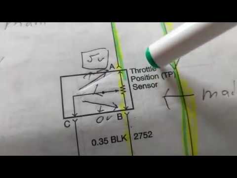
THROTTLE POSITION SENSOR explanation for wiring diagram
